Microcomputers/Microprocessors:

Hardware,
Software,
and Applications

John L. Hilburn
Paul M. Julich

Prentice-Hall Series In Automatic Computation © 1976

7.9. RCA COSMAC

The RCA COSMAC is a parallel, 8-bit, CMOS microprocessor, which is implemented in two IC packages [31-34]. The CMOS technology provides a high noise immunity that allows the processor to operate in electrically hostile environments. COSMAC is completely static, permitting the system clock to be controlled to facilitate interface with very slow memories or I/O devices. The processor operates from a single-phase clock having a frequency, which is variable from DC to 2 MHz.

Architecture

A block diagram of the COSMAC microprocessor is shown in Fig. 7.41. The system features a register array (R) consisting of sixteen 16-bit scratch-pad registers. Individual registers in the array are selected by a 4-bit code from one of the three registers labeled N, P, and X. The contents of any R register can be directed, via the buffer register A, to any one of the following:

1. The external memory (multiplexed onto eight memory address lines for direct addressing of 65,536 bytes).

2. The D register (either of the two bytes can be gated to D).

3. The increment/decrement circuit where it is increased or decreased by 1 and replaced in the selected 16-bit register.

RCA COSMAC block diagram
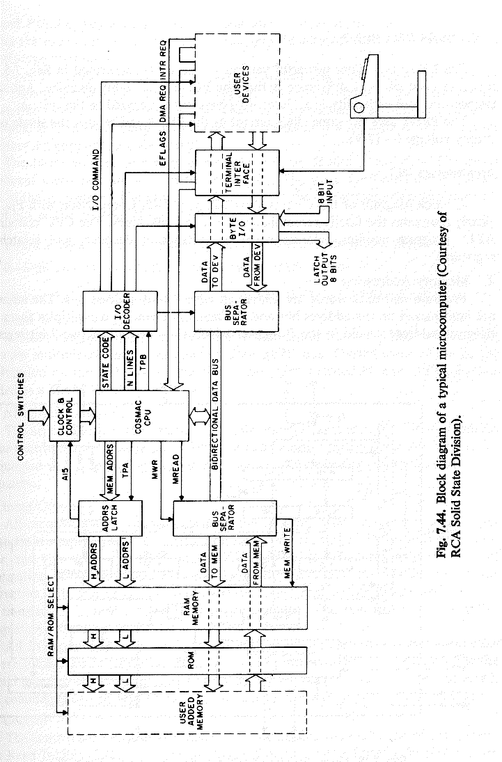
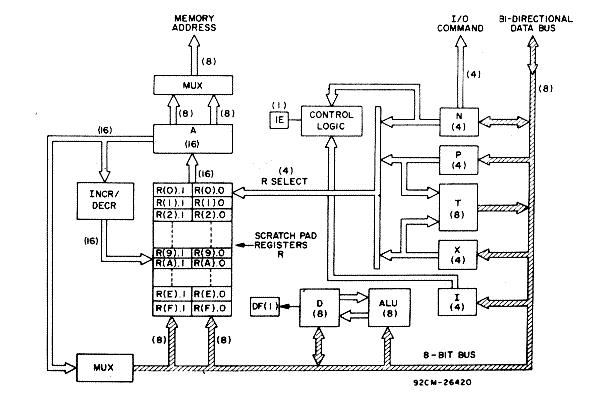
Fig. 7.41. Block diagram of the RCA COSMAC (Courtesy of RCA Solid State Division).

The three paths may operate independently or in various combinations in the same machine cycle.

Every COSMAC instruction consists of two 8-clock-pulse machine cycles (Fig. 7.42). The first cycle is a FETCH cycle, and the second is the EXECUTE cycle. In a FETCH cycle, the P register selects register R(P) as the current program counter. R(P) contains the memory address from which the instruction is to be fetched. When the instruction is read from memory, the higher-order four bits of the instruction byte are loaded into the I register and the lower-order four bits into the N register. The content of the program counter R(P) is automatically incremented to point to the next byte in the memory.

RCA COSMAC timing diagram
Fig. 7.42. Timing diagram for the RCA COSMAC (Courtesy RCA Solid State Division).

The X register selects one of the sixteen registers R(X) to point to the memory for an operand (or data).

The N register can perform the following, depending on the type of instruction fetched:

1. Designate one of sixteen registers in R to be acted upon during register operations.

2. Indicate to the I/O devices a command code or device-selection code for peripherals.

3. Indicate specific operations for ALU instructions, types of tests to be performed during branch instructions, or operating modes of interrupt-handling instructions.

4. Indicate the value of P to designate a new register to be used as the program counter R(P).

5. Indicate the value of X to designate a new register to be used as the data pointer R(X).

A programmer can assign the R registers in three ways: as program counters, as data pointers, or as scratch-pad registers for storing two bytes of data.

A. Program Counters

Any register can be the main program counter where the address of the selected register is held in the P register. Other R registers can be used as subroutine program counters. By a single instruction, the contents of P can be changed to affect a call to a subroutine. During an interrupt, register R(1) is used as the program counter for the interrupt-service routine. At all other times, any register can be designated as the program counter.

B. Data Pointers

Registers in R may be used as data pointers to indicate where data is located in memory. The register designated by X [i.e., R(X)] points to the data for the following instructions (see Appendix G):

1. ALU operations F0 through F7

2. Output instructions 60 through 67

3. Input instructions 68 through 6F

The register R(N), designated by N, points to the operand for instruction 4A (load D from memory) and instruction 5N (store D). The register R(P) (the program counter) is used as the data pointer for ALU instructions F8 through FF. During these instruction executions, the operation is referred to as data immediate.

Another important function of R as a data pointer occurs in a DMA operation. When a DMA-IN or DMA-OUT request is received, one machine cycle is "stolen" at the end of the EXECUTE machine cycle of the current instruction. Register R(0) is always used as the data pointer in a DMA operation (hardwired). At the end of each transfer, R(0) is incremented S0 that the processor is ready for the next DMA request. The DMA channel provides a simple method for entering data or programs into memory.

C. Data Registers

When registers in R are used to store data, four instructions are provided which allow D to receive from or write into either the higher-order or lower-order-byte portions of R(N), the register designated by N. By this mechanism (together with loading by data immediate), the program pointer and data pointer designations are initiated. Also, this technique allows scratch pad registers in R to hold general data.

D. Interrupt Servicing

Register R(1) is used as the program counter whenever interrupt servicing is performed. Following an interrupt request (when the interrupt enable, IE, is activated), the current EXECUTE machine cycle of an instruction is completed, the contents of P and X are stored in temporary register T, and P and X are set to new values. These values are hex digits 1 and 2 in P and X, respectively. The interrupt enable is automatically deactivated to inhibit other interrupts. The contents of T are saved by instruction 78 in the memory location pointed to by R(X), where X = 2. At the conclusion of the interrupt, the routine restores the pre-interrupt values of P and X via a single instruction. The programmer enables the interrupt-enable flip-flop if further interrupts are desired.

A register summary of the COSMAC is given in Table 7.6. The processor is fabricated in two dual in-line packages, as shown in the terminal assignment diagram of Fig. 7.43.

Instruction Set

The COSMAC instruction set given in Appendix G consists of fifty-nine instructions. Six instructions are provided for register operations that include Increment and Decrement R, and register exchanges between R and D. Two memory reference

Table 7.6 COSMAC REGISTER SUMMARY

Register No. of Bits Function

D 8 Data register (accumulator)
DF 1 Data flag (ALU carry)
R 16 1-of-16 scratch-pad registers
P 4 Designates program counter R(P)
X 4 Designates data pointer R(X)
N 4 Low-order instruction digit
I 4 High-order instruction digit
T 8 Temporary register; holds old X and P after interrupt
IE 1 Interrupt enable

RCA COSMAC terminal designations
Fig. 7.43. Terminal assignment Diagrams for the COSMAC (Courtesy of RCA Solid State Division).

instructions permit data exchanges between D and memory. Fifteen ALU instructions include Addition, Subtraction, Shift, Load, and logical (AND, OR, EXCLUSIVE-OR) operations. Fourteen branching instructions allow Skip and conditional and unconditional branching. Six control instructions consist of Idle (halt), Set P or X, Return, Disable Interrupt, and Save (contents of T). Sixteen input/output byte transfer instructions complete the instruction set.

Microcomputer Systems

A typical microcomputer system employing the COSMAC microprocessor is shown in Fig. 7.44. Support hardware necessary for the CPU includes a bus separator, I/O control circuits, clock, and an address latch. Memory, consisting of ROM and/or RAM, can be provided to a maximum of 65,536 bytes.

A prototyping system based on the COSMAC processor is the RCA Microprocessor Hardware Support Kit (COSMAC Microkit). The Microkit consists of a CPU, clock and control, bus separator, address latch, 512-byte RAM and PROM, I/O decoder, terminal, and byte I/O printed circuit cards. These cards are housed in a 19-in, rack having a power supply and front panel configured with basic controls. The PROM card contains a utility program which performs commonly required functions: program loading, memory dump, modification of memory locations, paper tape punch, saving of registers, and start of program execution at a specified location. Additional memory can be added to the basic system.
Software support for the Microkit includes an editor, assembler, and simulator/debugger. The software support system is available in two forms. It is supplied as a 9-track, 800-BPI, IBM-compatible tape, written in standard FORTRAN IV for installation on a variety of computers. It is also available on the General Electric Information Services International Network for use by time-sharing customers.

Comments

The COSMAC processor is a static CMOS device that offers the advantages of high noise immunity and operation from a single-phase clock. The clock frequency is variable from DC to 2 MHz. The processor can be operated from a single power supply having a voltage range of 4 to 12 V. The internal voltage supply (VDD) is isolated from the I/O supply (VCC) so that the processor may operate at maximum speed (VDD = 10 V) while interfacing with various IC families such as TTL.

The CPU has sixteen 16-bit R registers, each of which may be used for data holding, as an index register, or as a program counter. The depth of an on-chip pushdown stack is therefore limited by other uses of these registers, as specified by the user. Since the program counter in one program can be treated as an operand in another, storing register contents into main storage can extend the pushdown stack of return addresses.

The processor has four I/O flag inputs (EF1 through EF4) to enable the I/O controllers to transfer status information to the CPU. These levels can be tested by conditional branch instructions and can be used to establish priorities for interrupt. The processor also has a useful on-chip DMA facility. Interfaces for communications networks, keyboards, TV displays, and floppy disks have been constructed utilizing the interrupt and DMA capabilities of the device [34].

Typical Microcomputer
Appendix
G INSTRUCTION SET FOR THE RCA COSMAC
(Courtesy of RCA Semiconductor Division.)

Instruction Set

The COSMAC instruction summary is given in Table I. Hexadecimal notation is used to refer so the 4-bit binary codes. Many of the instructions have been discussed in the Architecture section. Symbols used are:

R(W): Register designated by W, where W = N, or X, or P
R(W).0: Lower-order byte of R(W)
R(W).1: Higher-order byte of R(W)

Operation Notation
operation notation
This notation means: The memory byte pointed to by R(N) is loaded into D, and R(N) is incremented by 1.

Table I - Instruction Summary
table 1a
table 1b
table 1c
*These are the only operations that modify DF. DF is set or reset by an ALU carry during add or subtract. Subtraction is by
2's complement:

Note: This type of abbreviated nomenclature is used when programs are designed with the aid of the COSMAC Assembler Simulator/Debugger System, which is available on commercial timesharing systems. Refer to "Program Development Guide for the COSMAC Microprocessor" for details.

Test and Branch

The Test and Branch instructions can branch unconditionally, test for D = 0 or D = 1, test for DF = 0 or DF = 1, or can test the status of the four I/O flags. A "successful" branch loads the byte following the instruction into the lower-order byte position of the current program counter, effecting a branch within the current 256-byte "page" of memory. If the test to branch is not successful, the next instruction in sequence is executed.